Why Decode a QR Code Manually?
Decoding a QR code by hand is genuinely impractical for everyday use — but as a learning exercise, it is one of the best ways to understand what is happening inside those black-and-white grids. Developers integrating QR functionality into apps, engineers debugging scanner failures, and curious technologists all benefit from a working knowledge of the underlying structure.
This walkthrough covers Version 1 QR codes (the smallest variant, 21×21 modules), which are the only size realistically decodable by a human in a reasonable amount of time. Everything described here is grounded in the ISO/IEC 18004 standard. For a full reference on QR versions, error correction levels, and module counts, see the QR code technical specifications pillar.
Print the QR code at a large size (at least 10 cm × 10 cm) on plain paper. Use a ruler and pencil to draw a grid overlay that labels rows and columns 0–20 from the top-left. Mark each dark module as 1 and each light module as 0. This grid is your working document for every step below.

QR Code Anatomy Quick-Ref
Before reading any bits, you need to know which modules are functional (fixed structural elements) and which are data modules (the ones you will actually decode). Functional modules are never part of the encoded payload.
- Finder patterns: Three 7×7 corner squares (top-left, top-right, bottom-left). Each has a specific 1:1:3:1:1 dark/light ratio that scanners use for location and orientation.
- Separators: One-module-wide white borders surrounding each finder pattern, keeping them visually isolated from adjacent data.
- Timing patterns: Alternating dark/light strips running horizontally (row 6) and vertically (column 6) between the finder patterns. They calibrate the module grid alignment.
- Format information: Two 15-bit strips adjacent to the finder patterns that encode error correction level and mask pattern ID.
- Dark module: A single always-dark module at row 8, column 8 (bottom-right of the top-left finder separator).
- Data and error-correction modules: Everything else. This is what you decode.
Understanding the full structure of these regions in precise coordinates is covered in the technical specifications guide. For now, the key point is: shade all functional modules on your grid before you touch a single data bit.
Step 1: Find the Finder Patterns
The three finder patterns are your anchors. On your 21×21 grid, each occupies a 7×7 block:
- Top-left: rows 0–6, columns 0–6
- Top-right: rows 0–6, columns 14–20
- Bottom-left: rows 14–20, columns 0–6
Each finder pattern is a solid 3×3 dark centre, surrounded by a white ring, surrounded by a solid dark outer border. The absence of a fourth finder pattern at the bottom-right corner is intentional — this asymmetry is what tells the decoder the orientation of the code.
Around each finder pattern is a one-module-wide white separator. Mark all finder and separator modules on your grid in a distinct colour (blue or green work well). These are off-limits for data reading.
Scan each row of a finder pattern from left to right and count the run-lengths of dark and light modules. You should always get the sequence 1, 1, 3, 1, 1 (dark, light, dark, light, dark). If you don't, you may have misidentified a module or your grid overlay is misaligned. Re-check before proceeding.
Step 2: Determine Version and Size
For Version 1, you know the code is 21×21 by counting modules. The version number V is related to size by the formula: size = (V × 4) + 17. So 21 modules across means (21 − 17) ÷ 4 = 1. Version 1 confirmed.
Versions 2 and above also encode their version number explicitly in additional version information modules near the top-right and bottom-left finder patterns. Version 1 does not have version information modules, so there is nothing to read here — just note the version and continue.
Also mark the timing patterns on your grid now: row 6, columns 8 through 12 (the horizontal strip), and column 6, rows 8 through 12 (the vertical strip). These alternate dark-light-dark and are always fixed regardless of data content.
Step 3: Read the Format Information
Format information is stored in two identical 15-bit sequences — one adjacent to the top-left finder pattern, one split between the other two. Reading either copy is sufficient; both encode the same data as a redundancy check.
For the top-left copy, read the following 15 modules in order (row, column):
Write down the 15-bit string you read. Now XOR it with the mask value 101010000010010 (in binary). This removes a fixed XOR mask that was applied during encoding to prevent the format information area from accidentally resembling a data pattern.
The resulting 15 bits break down as:
- Bits 14–13: Error correction level.
01= L,00= M,11= Q,10= H. - Bits 12–10: Mask pattern ID (0–7). You will need this in the next step.
- Bits 9–0: BCH error-correction bits for the format string itself (you can ignore these for manual decoding if your reading is accurate).
Note both values: the error correction level tells you how many codewords are data vs. error-correction; the mask ID tells you how to undo the masking applied to data modules. The eight mask formulas are detailed in the technical specifications article.
Step 4: Apply the Mask Pattern
QR encoders apply one of eight mask patterns to data modules to break up problematic visual patterns (large solid blocks, checkerboards, runs that look like finder patterns) that would confuse scanner algorithms. To decode, you must reverse the mask by applying it again — XOR is its own inverse, so applying the same mask formula a second time restores the original bits.
The eight mask condition formulas use the row index i and column index j of each module (0-indexed from top-left). A module is inverted if its (i, j) coordinates satisfy the mask formula:
Go through every data module on your grid (all modules not already marked as functional). For each one, evaluate whether its (i, j) satisfies the mask formula you identified in Step 3. If it does, flip the bit: 0 becomes 1, 1 becomes 0. If it does not satisfy the formula, leave the bit unchanged.
After this step, your grid holds the true data bits as they were before masking. Mask patterns are closely related to the encoding pipeline discussed in QR code encoding modes.
Step 5: Extract Data Bits in Zigzag Order
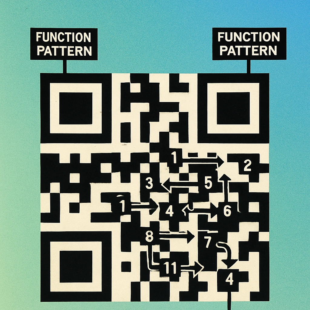
Data modules are read in a specific zigzag pattern defined by the standard. Starting from the bottom-right corner of the code, data is read in two-column-wide vertical strips. The reading direction alternates: the first strip reads bottom-to-top; the second (immediately to the left) reads top-to-bottom; the third reads bottom-to-top again; and so on.
Within each two-column strip, you read the right column first, then the left column — so you collect two bits per row position before moving to the next row. The vertical timing column (column 6) is skipped entirely and the strip narrows to account for it.
Mark strips on your grid with alternating light pencil shading before reading. Label each strip 1, 2, 3... from right to left, noting the direction arrow. Then trace each strip in order and write down the bit value of every non-functional module you encounter. Collect bits into groups of 8 to form codewords.
For a Version 1 QR code with error correction level M, you will collect 26 codewords in total: 16 data codewords and 10 error-correction codewords. You only need the first 16 data codewords to recover the payload (the error-correction codewords are for checking and repairing, not decoding from scratch when the code is undamaged).
The relationship between data capacity, version, and error correction levels is covered in depth in our article on Reed-Solomon error correction in QR codes.
Step 6: Decode the Encoding Mode and Payload
With your raw data bits in hand, the final stage is interpreting them as structured data. The first four bits of your bit stream are the mode indicator:
0001— Numeric mode (digits 0–9 only)0010— Alphanumeric mode (uppercase A–Z, digits, and nine special characters)0100— Byte mode (ISO 8859-1 or UTF-8)1000— Kanji mode0000— End of message terminator
After the mode indicator, the next group of bits is the character count indicator. Its length depends on the mode and version (for Version 1 numeric: 10 bits; alphanumeric: 9 bits; byte: 8 bits).
Then come the actual character bits. In numeric mode, each group of 10 bits encodes three decimal digits (values 0–999). In alphanumeric mode, 11 bits encode two characters using a 45-character alphabet where A=10, B=11, ... space=36, $=37, %=38, *=39, +=40, -=41, .=42, /=43, :=44. In byte mode, each 8-bit codeword is a single ISO 8859-1 byte. Full encoding tables are in the encoding modes guide.
Skip the Manual Work — Generate Instantly
Now you know exactly what goes into a QR code. Create and download one in seconds with our free online tool — or get the Mac app for offline generation.
Putting It All Together
To summarise the complete manual decode pipeline in one place:
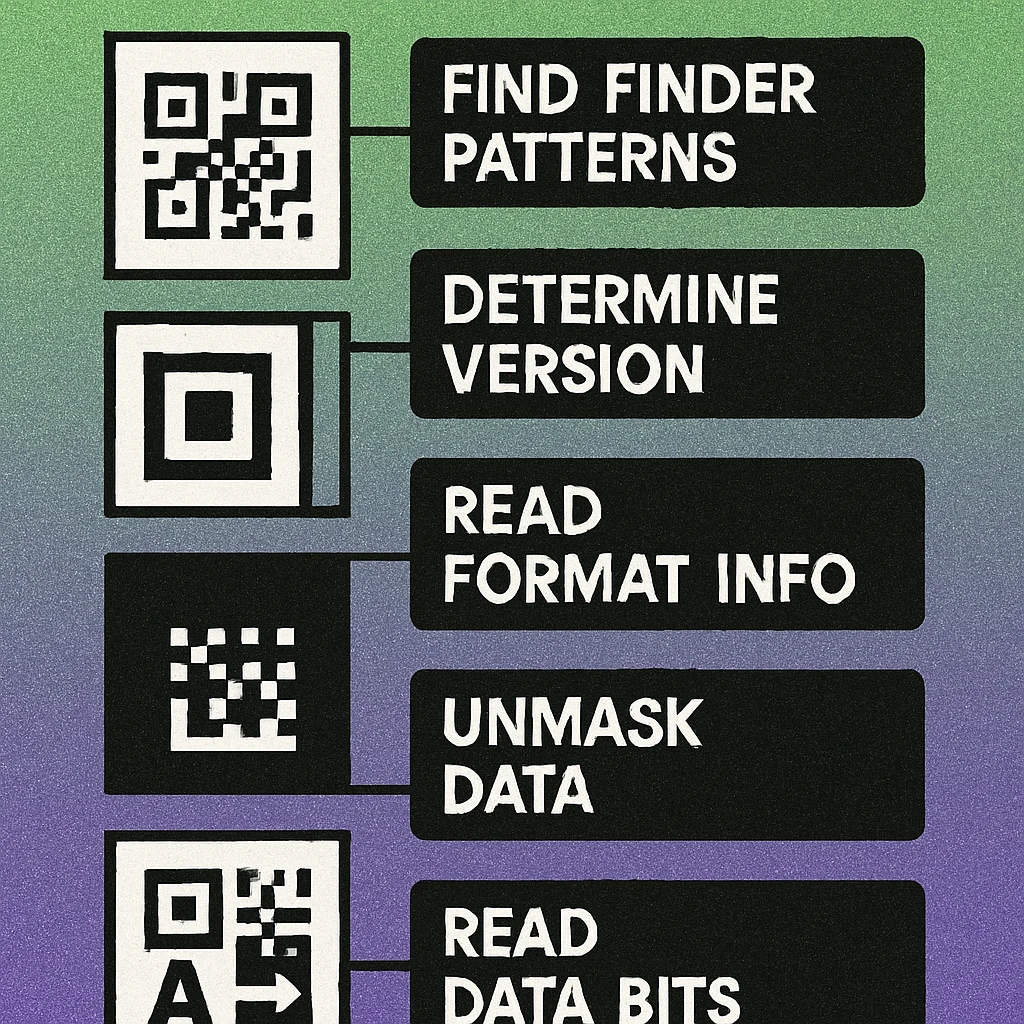
Six Steps to Decode a QR Code by Hand
Locate finder patterns. Identify the three 7×7 corner targets and their surrounding separators. Mark all functional modules on your grid. Confirm the 1:1:3:1:1 dark/light run ratio in each finder row and column.
Count modules to determine version. Count modules across one side, subtract 17, divide by 4. Mark timing patterns (row 6, column 6) on your grid.
Read and decode format information. Extract the 15-bit format string from modules adjacent to the top-left finder pattern. XOR with 101010000010010. Extract error correction level (bits 14–13) and mask ID (bits 12–10).
Undo the mask pattern. For every non-functional module, evaluate the mask formula using the module's (row, column) coordinates. Flip any module that satisfies the formula. Leave others unchanged.
Extract data bits in zigzag order. Read two-column strips from the bottom-right, alternating direction, right-column-first within each strip. Skip functional modules. Group every 8 bits into a codeword. Stop after the data codewords (ignore error-correction codewords).
Decode mode indicator and character data. Read the first 4 bits as the mode, the next n bits as the character count, then decode the remaining bits using the mode-specific encoding table to recover the original text or URL.
Manual decoding reveals that a QR code is really a carefully structured binary file printed as a two-dimensional image. The finder patterns give it spatial orientation, the format information strip describes how to read the rest, the mask keeps the visual pattern scanner-friendly, and the zigzag reading order packs data efficiently regardless of the code version. Understanding each layer makes debugging real-world scan failures — and appreciating the full QR specification — much more intuitive.
Frequently Asked Questions
Yes, for small QR codes (Version 1, 21×21 modules) it is genuinely possible to decode by hand with patience and a printed grid. You need to identify the finder patterns, extract the format information string, apply the mask pattern, then read the data codewords in zigzag order. It takes around 30 to 60 minutes for a short alphanumeric payload and is an excellent way to deeply understand how QR codes work internally.
Finder patterns are the three 7×7 square targets located in the top-left, top-right, and bottom-left corners of every QR code. Each consists of a 3×3 solid dark square surrounded by a white border and then another dark border. Their distinctive 1:1:3:1:1 dark-to-light ratio makes them easy for scanners to detect regardless of rotation or orientation, and they are also what tells the decoder where the code begins and how it is oriented.
A mask pattern is an XOR operation applied to the data and error-correction modules before the QR code is finalised. There are eight possible mask patterns, each defined by a mathematical formula applied to module coordinates. Masking is used to prevent large areas of same-colour modules which would confuse scanners. When decoding manually, you must read the mask pattern ID from the format information strip, then XOR every data module with the corresponding formula to recover the original bit values.
After removing functional patterns and applying the mask, data bits are read in two-column-wide vertical strips starting from the bottom-right corner of the code and moving upward. When the strip reaches the top, the next two-column strip starts immediately to the left and reads downward. Within each two-column strip, bits are read right-column-first then left column, alternating as the strip moves. This zigzag creates a continuous stream of bits from which 8-bit codewords are assembled in sequence.