QR Code Anatomy: What Every Module Does
A QR code is not a random scatter of dark and light squares. Every module — the smallest individual unit in the grid — serves a specific purpose defined by the ISO/IEC 18004 standard. Understanding the anatomy of a QR code is essential for anyone building generators, designing custom codes, or troubleshooting scan failures. If you're new to QR codes entirely, our complete QR code guide covers the basics before diving into these technical details.
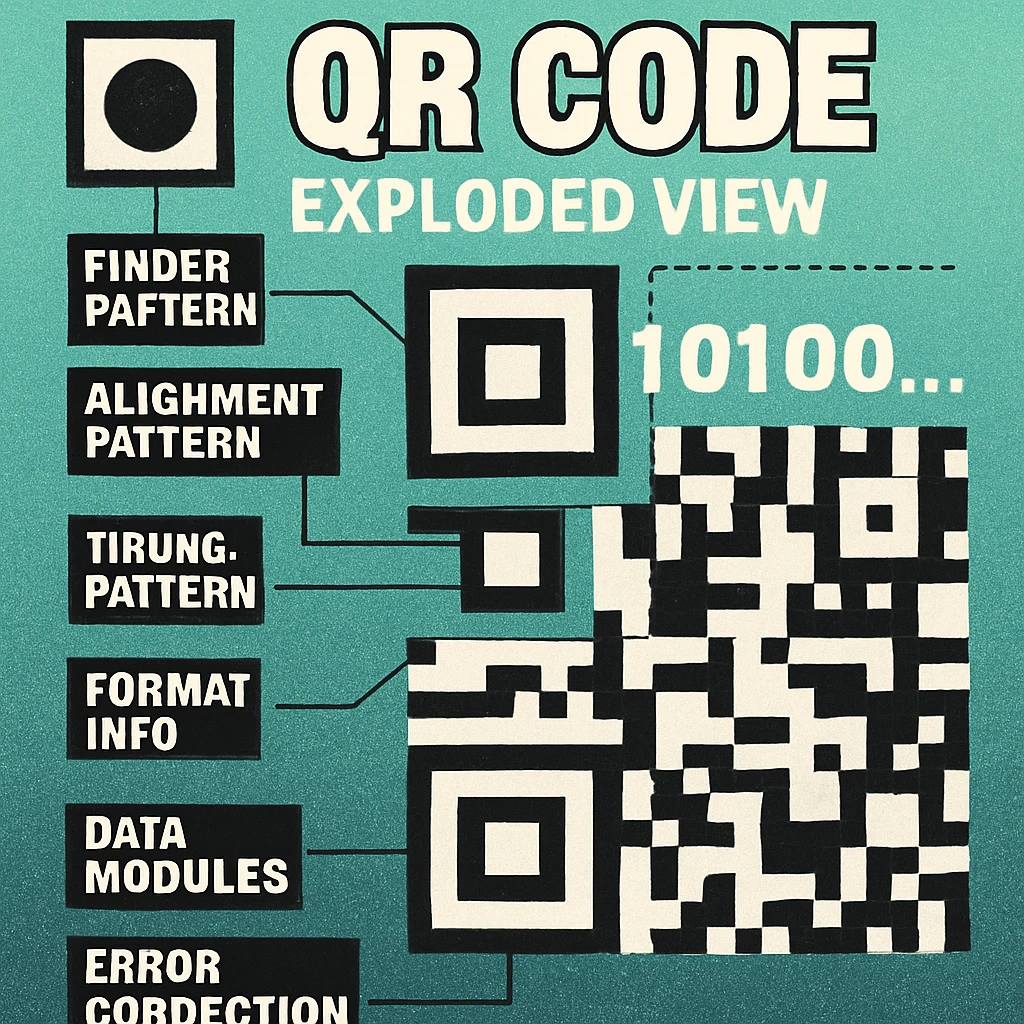
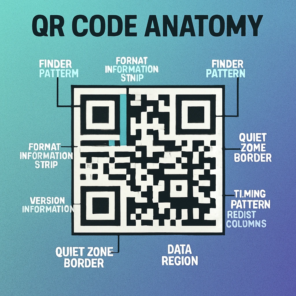
Every QR code is composed of seven distinct functional areas, each playing a critical role in how the code is located, oriented, decoded, and error-corrected by scanning software. These areas are: finder patterns, alignment patterns, timing patterns, format information, version information, the data area, and the quiet zone.
QR codes are defined by ISO/IEC 18004:2015. This international standard specifies symbol structure, data encoding, error correction, and the reference decoding algorithm. Everything described in this article traces back to that specification.
Finder Patterns: How Scanners Locate the Code
The three large squares at the top-left, top-right, and bottom-left corners of every QR code are the finder patterns. These are the most visually distinctive part of the code and the first thing a scanner identifies. Each finder pattern is a 7×7 module structure with a precise geometry: a 3×3 dark centre, surrounded by a one-module-wide light ring, surrounded by a one-module-wide dark border.
This nested square design creates a unique ratio of dark-light-dark-light-dark (1:1:3:1:1) that a scanner can recognise from any direction and at any rotation angle. No matter how a QR code is oriented in physical space — upside down, at 45 degrees, photographed at an angle — the finder patterns allow the decoding software to determine the code's location, rotation, and scale in a single pass.
Between the finder patterns sit separator modules — a one-module-wide band of light modules that isolates each finder pattern from the data area. This separation is critical: without it, data modules adjacent to the finder could be mistakenly interpreted as part of the finder pattern itself, causing decode errors.
The bottom-right corner of a QR code is intentionally left without a finder pattern. Instead, a smaller alignment pattern occupies this quadrant in Version 2 and above. This asymmetry is deliberate — it gives the scanner an unambiguous way to determine the code's orientation (distinguishing a 0-degree read from a 180-degree read).
Alignment Patterns, Timing Patterns, and Structural Modules
Alignment Patterns
Starting from Version 2 (25×25 modules), QR codes include one or more alignment patterns. These are smaller 5×5 module markers placed at regular intervals across the code. Their purpose is to compensate for geometric distortion — the warping that occurs when a code is printed on a curved surface, photographed at an angle, or physically bent. The number of alignment patterns grows with the version: Version 2 has one, Version 7 has six, and Version 40 has 46.
Each alignment pattern consists of a single dark module at the centre, surrounded by a one-module light ring, surrounded by a one-module dark ring. The scanner uses these fixed reference points to build a distortion correction grid across the entire code, enabling accurate module sampling even when the image is significantly warped.
Timing Patterns
Two lines of alternating dark and light modules connect the finder patterns — one running horizontally between the top-left and top-right finders, and one running vertically between the top-left and bottom-left finders. These are the timing patterns. They allow the scanner to determine the exact coordinate grid of the code by counting modules between known positions. Without timing patterns, the decoder would have no way to resolve module positions in areas far from the finder patterns.
Format Information
Two copies of a 15-bit format information string are embedded adjacent to the finder patterns. This string encodes two pieces of metadata: the error correction level (L, M, Q, or H) and the mask pattern number (0 through 7). The format information is protected by a BCH (Bose-Chaudhuri-Hocquenghem) error-correcting code, ensuring that even if part of it is damaged, the scanner can still determine how to decode the data area. The duplication provides additional redundancy.
Version Information
For Version 7 and above, two copies of an 18-bit version information block are placed near the finder patterns. This tells the scanner which version of QR code it is reading, so it can determine the correct module grid size and alignment pattern positions. Versions 1 through 6 omit this block because the grid size is small enough for the scanner to infer the version from the overall dimensions alone.
Data Area
Everything that is not a finder pattern, alignment pattern, timing pattern, format information, version information, or separator module is part of the data area. This is where the actual encoded payload lives, along with the Reed-Solomon error correction codewords. Data modules are placed in a specific two-column zigzag pattern starting from the bottom-right corner and working upward and leftward. For a detailed look at how data actually flows through this area, see our article on decoding a QR code manually.
Quiet Zone
The quiet zone is the mandatory empty border surrounding the entire QR code. The specification requires it to be at least four modules wide on all four sides. This margin gives the scanner a clean edge to detect where the code starts and ends. Cropping or reducing the quiet zone is one of the single most common causes of scan failure, especially in print applications where the code is placed close to other visual elements. For more on sizing and spacing, see our data capacity and sizing guide.
The Version System: Versions 1 Through 40
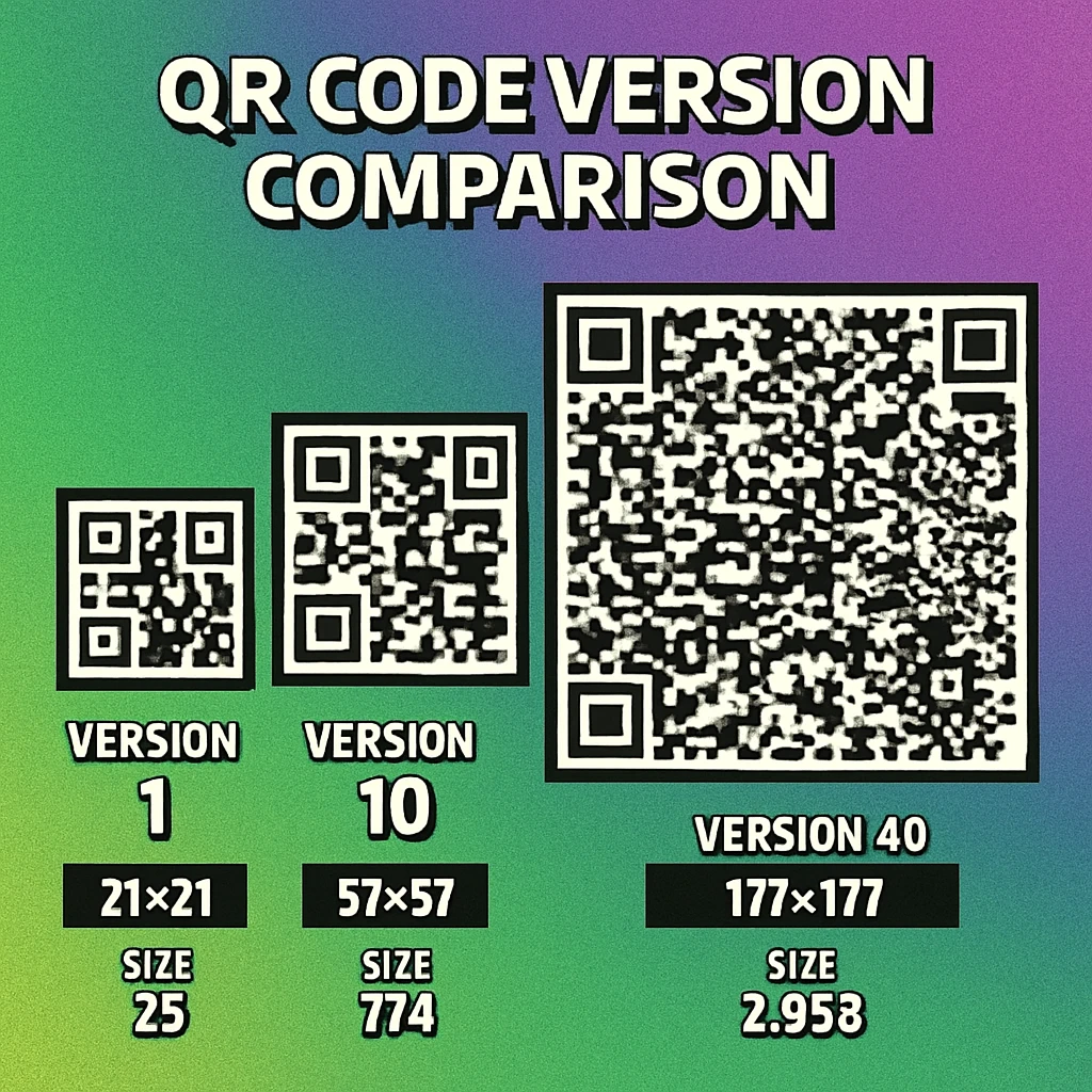
QR codes come in 40 versions. The version number directly determines the grid size: Version 1 is 21×21 modules, and each subsequent version adds 4 modules per side. So Version 2 is 25×25, Version 3 is 29×29, and so on up to Version 40 at 177×177 modules — a grid of 31,329 individual modules.
The formula is straightforward: for any version V, the grid size is (4V + 17) × (4V + 17) modules. This predictable scaling is what allows the version system to cover an enormous range of data capacities while maintaining a single consistent specification.
| Version | Grid Size | Total Modules | Numeric (EC L) | Alphanumeric (EC L) | Byte (EC L) |
|---|---|---|---|---|---|
| 1 | 21 × 21 | 441 | 41 | 25 | 17 |
| 2 | 25 × 25 | 625 | 77 | 47 | 32 |
| 5 | 37 × 37 | 1,369 | 202 | 122 | 84 |
| 10 | 57 × 57 | 3,249 | 652 | 395 | 271 |
| 20 | 97 × 97 | 9,409 | 2,061 | 1,249 | 858 |
| 40 | 177 × 177 | 31,329 | 7,089 | 4,296 | 2,953 |
In practice, the vast majority of QR codes use Versions 1 through 10. A typical URL QR code (40–80 characters) fits comfortably in Version 3 or 4 with error correction level M. Higher versions are needed for large payloads like vCard contact data, Wi-Fi configurations with long passwords, or bulk encoding scenarios. For a thorough look at how much data fits in each version, see our data capacity deep dive.
Higher version numbers mean denser grids. A Version 40 code printed at the same physical size as a Version 2 code has individual modules roughly 8 times smaller. This means higher versions require higher print resolution (at least 300 DPI) and larger minimum print sizes to remain scannable. See our print resolution and DPI guide for specifics.
Error Correction Levels: L, M, Q, and H
Every QR code includes Reed-Solomon error correction codewords alongside the actual data. This redundancy allows the code to be read correctly even when part of it is damaged, obscured, or missing. The ISO specification defines four error correction levels, each trading data capacity for damage tolerance.
| Level | Recovery Capacity | Overhead | Best For |
|---|---|---|---|
| L (Low) | ~7% of codewords | Lowest | Clean digital displays, maximum data density |
| M (Medium) | ~15% of codewords | Moderate | General purpose, the default for most generators |
| Q (Quartile) | ~25% of codewords | High | Outdoor use, industrial labels, moderate damage risk |
| H (High) | ~30% of codewords | Highest | Logo overlays, harsh environments, maximum resilience |
The relationship between error correction and capacity is inverse: choosing a higher error correction level at the same version reduces the number of data characters you can encode. For example, a Version 5 code with EC level L holds 154 alphanumeric characters, but the same Version 5 with EC level H holds only 60. If your payload is fixed, increasing error correction may force the generator to step up to a higher (larger, denser) version.
Error correction level H is particularly important for QR codes with embedded logos, because the logo physically covers data modules. The 30% recovery capacity of level H is what makes logo overlays viable. For a mathematical deep dive into how Reed-Solomon codes actually achieve this recovery, see our article on how Reed-Solomon error correction works.
For a broader look at how error correction interacts with design choices like colour, shape, and size, see our dedicated error correction guide.
Generate QR Codes with Full Control
Choose your error correction level, data type, and output format. Free, fast, and no signup required.
Data Encoding: The Four Primary Modes
QR codes don't store raw text directly. The payload is first encoded using one of four modes, each optimised for a specific type of character set. The choice of encoding mode directly affects how efficiently the data is packed into the available module grid — and therefore how much data a given version can hold.
| Mode | Characters Supported | Bits per Character | Example Use |
|---|---|---|---|
| Numeric | 0–9 | ~3.33 (10 bits per 3 digits) | Phone numbers, serial numbers, numeric IDs |
| Alphanumeric | 0–9, A–Z, space, $, %, *, +, -, ., /, : | ~5.5 (11 bits per 2 chars) | Short URLs (uppercase), product codes |
| Byte | Any ISO 8859-1 byte (0–255) | 8 | URLs, UTF-8 text, binary data, vCards |
| Kanji | Double-byte Shift JIS characters | 13 | Japanese text (Kanji, Kana) |
Numeric mode is the most efficient, packing three decimal digits into just 10 bits. This means a QR code encoding a purely numeric string (like a phone number or tracking code) can hold roughly twice as much data as the same code encoding arbitrary text in byte mode. Encoders automatically select the optimal mode for the data being encoded.
Alphanumeric mode supports uppercase letters, digits, and a limited set of symbols. Note that lowercase letters are not included — any URL or text containing lowercase characters will be encoded in byte mode, which is less efficient. This is why some QR generators automatically uppercase URLs when possible: it allows alphanumeric encoding and reduces the version required.
Byte mode is the general-purpose fallback. Every byte value from 0 to 255 is supported, making it suitable for URLs, UTF-8 encoded text, vCard data, and any other binary content. Most real-world QR codes (URLs, contact info, Wi-Fi credentials) use byte mode because their content includes lowercase characters or special symbols outside the alphanumeric set.
Kanji mode is specific to Japanese text encoded in Shift JIS. It encodes each double-byte character in 13 bits rather than the 16 bits that byte mode would require, yielding a meaningful space saving for Japanese-language payloads.
A single QR code can contain multiple encoding segments using different modes. Smart encoders analyse the payload and switch modes mid-stream to minimise total bit length. For a complete walkthrough of how each mode works at the bit level, see our article on QR code encoding modes.
If you're building a QR encoder, implementing mixed-mode encoding is the single biggest optimisation you can make. A URL like HTTPS://EXAMPLE.COM/12345 can use alphanumeric mode for the uppercase portion and numeric mode for the trailing digits, saving enough bits to drop an entire version level in some cases. Our Python, JavaScript, and Swift tutorials cover library-level implementation details.
Masking Patterns: Balancing the Grid
After data and error correction codewords are placed in the module grid, one final transformation is applied: a mask pattern. The QR specification defines eight mask patterns (numbered 0 through 7), each described by a simple mathematical formula that determines which data modules should be flipped from dark to light or vice versa.
Masking exists to solve a real problem. Without it, certain data payloads would produce large uniform blocks of dark or light modules, or create patterns that accidentally look like finder patterns, timing patterns, or alignment patterns. These visual artefacts confuse scanners and increase the error rate. The mask disrupts these problematic patterns by redistributing the module values across the grid.
The eight mask formulas operate on the row (i) and column (j) coordinates of each data module:
| Mask | Formula (flip if true) | Visual Effect |
|---|---|---|
| 0 | (i + j) mod 2 = 0 | Checkerboard |
| 1 | i mod 2 = 0 | Horizontal stripes |
| 2 | j mod 3 = 0 | Vertical stripes (every 3rd column) |
| 3 | (i + j) mod 3 = 0 | Diagonal pattern |
| 4 | (i/2 + j/3) mod 2 = 0 | Block checkerboard |
| 5 | (i*j) mod 2 + (i*j) mod 3 = 0 | Star burst |
| 6 | ((i*j) mod 2 + (i*j) mod 3) mod 2 = 0 | Diamond pattern |
| 7 | ((i+j) mod 2 + (i*j) mod 3) mod 2 = 0 | Mixed diagonal |
The encoder applies each of the eight masks to the data area, evaluates the result against four penalty rules (which penalise large same-colour blocks, patterns resembling finder patterns, and uneven dark/light ratios), and selects the mask that produces the lowest total penalty score. The selected mask number is then recorded in the format information so the decoder knows which mask to reverse.
Masking only affects data and error correction modules. Finder patterns, alignment patterns, timing patterns, format information, and version information are never masked — they must remain fixed for the scanner to read them correctly.
For a hands-on demonstration of how masking transforms a real QR code, our guide on decoding a QR code by hand walks through the mask removal step in detail.
Developer Resources: Cluster G Articles
This pillar article is the foundation of our Technical & Developer cluster. The following spoke articles explore individual topics in depth:
All Cluster G Articles
Encoding Modes: Numeric, Alpha, Byte, Kanji — How QR codes encode different character sets and how mode selection affects capacity.
How Reed-Solomon Error Correction Works — The math behind QR code damage recovery: polynomials, Galois fields, and correction levels.
Generate QR Codes with Swift — Use CIFilter and Core Image to generate QR codes natively in Swift for iOS and macOS.
Generate QR Codes with Python — Create QR codes in Python with qrcode, Pillow, and segno — from pip install to PNG export.
Generate QR Codes with JavaScript — Client-side and Node.js QR generation with qrcode.js, qr-code-styling, and node-qrcode.
Using CIFilter to Create QR Codes on macOS — Deep dive into CIQRCodeGenerator: customisation, scaling, colour, and SwiftUI integration.
QR Code Generator API for Developers — REST API reference for generating QR codes programmatically: endpoints, parameters, and examples.
GS1 Digital Link & QR Codes — How GS1 Digital Link URIs unify product identification and QR codes into one scannable standard.
How to Decode a QR Code Manually — Step-by-step guide to reading a QR code by hand: finder patterns, masking, and bit extraction.
Frequently Asked Questions
There are 40 versions of QR codes, numbered 1 through 40. Version 1 is a 21×21 module grid and each subsequent version adds 4 modules per side, so Version 40 is a 177×177 module grid. Higher versions store more data but produce larger, denser codes that require higher print resolution.
The four error correction levels are L (Low, ~7% recovery), M (Medium, ~15% recovery), Q (Quartile, ~25% recovery), and H (High, ~30% recovery). Higher levels let the code survive more damage or obstruction but reduce the amount of data that can be stored at a given version size.
Finder patterns are the three large square markers located in the top-left, top-right, and bottom-left corners of every QR code. Each is a 7×7 module structure with a nested dark-light-dark ring design. Scanners use these patterns to locate and orient the QR code regardless of rotation.
The four primary encoding modes are Numeric (digits 0–9, most efficient at ~3.3 bits per character), Alphanumeric (digits, uppercase A–Z, and nine symbols, ~5.5 bits per character), Byte (any ISO 8859-1 character or UTF-8 data, 8 bits per character), and Kanji (double-byte characters for Japanese text, 13 bits per character). A single QR code can mix modes to optimise capacity.
The quiet zone is the mandatory blank margin surrounding the entire QR code. The ISO 18004 specification requires it to be at least four modules wide on all sides. This empty space helps scanners distinguish the QR code boundary from surrounding content. Cropping or violating the quiet zone is one of the most common causes of scan failure.
Masking patterns are applied to the data area of a QR code to break up large uniform regions and ensure an even balance of dark and light modules. Without masking, certain data payloads could produce patterns that confuse scanners. The encoder evaluates all eight mask patterns and selects the one that produces the most balanced result.
At Version 40 with error correction level L, a QR code can store up to 7,089 numeric characters, 4,296 alphanumeric characters, or 2,953 bytes of binary data. However, most practical QR codes use Versions 1–10 with error correction M or higher, which means real-world capacity is typically between 25 and 500 characters.